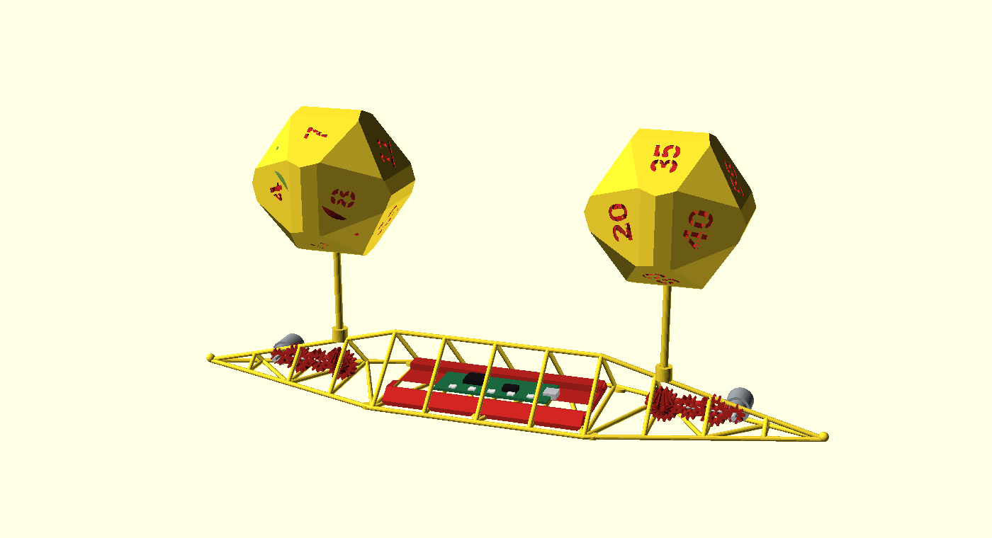
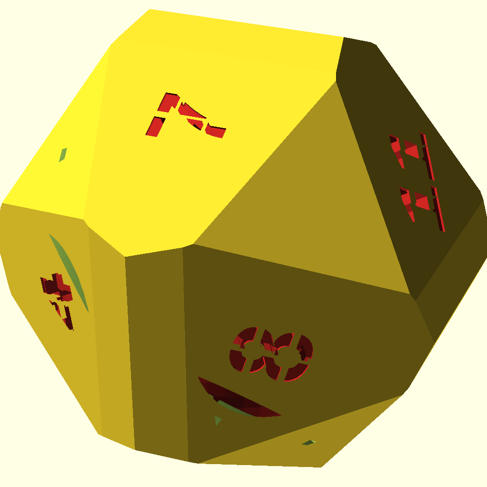
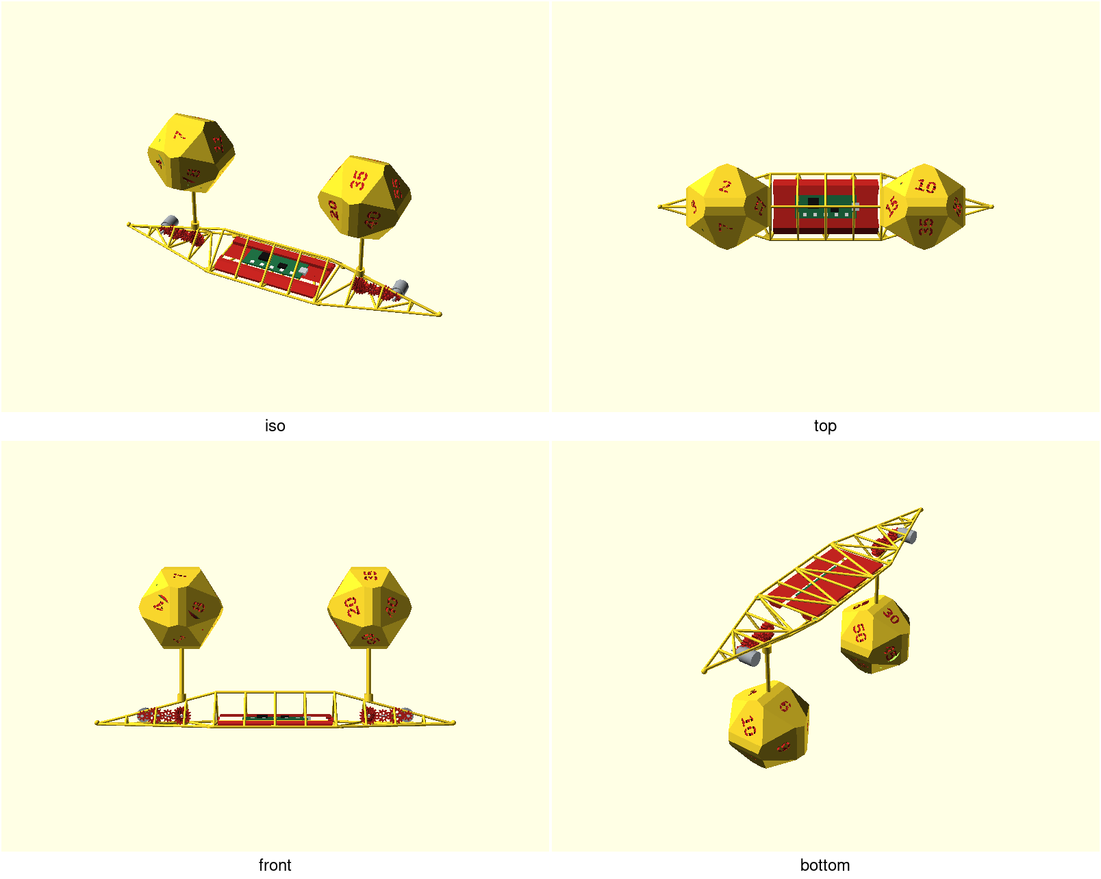
A desk clock that tells the time on two slowly tumbling faceted balls: the left ball shows the hour, the right ball the minutes in five-minute steps, each number sitting on one of twelve pentagon plaques. A helical slot cut through each shell frames the gears inside, so the mechanism is the ornament. This is a clean-room re-creation, in print-bench, of the "ovodyo" clock by Mectolab — built as a v0 base the improvement backlog (#599) refines.
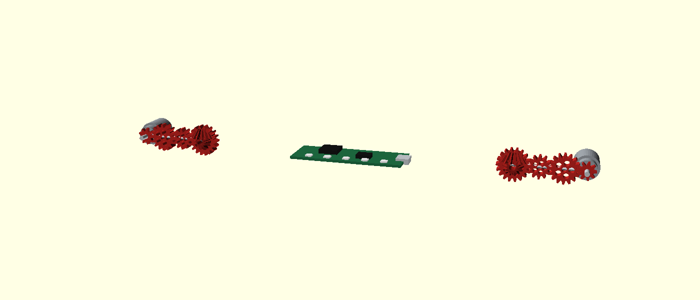
v0 — a working substrate, not the finished clock. The geometry renders, gates and slices, and the signature look is here: chunky faceted dice-balls (chamfered dodecahedra — twelve flush pentagon faces plus triangular corner facets), bold numerals cut clean through each shell to a red interior (stencilised so no counter drops out), and the reference's exposed gearing in the base — a geared stepper and reduction gear-train at each pod, a bevel take-off up each stalk, and a central electronics bay. The base drivetrain and the red interior are shown as preview-only coloured parts (a single-material print is one colour; the two colours are the intent). The balls now screw together on a captive threaded seam (#602) and the base carries a red structural core — a ballast keel with sealed shot pockets (#603). Several things are still deliberately simplified and tracked as issues: the base gears represent the drive but aren't a real meshing involute differential; there is no reusable space-frame library (#604); the slot isn't yet a tunable brand module (#601); the CoG/tip-over check now runs from
ci.cogas an advisory WARN (it does not fail the gate). The first gate emit on tipd8d9cf5measured STABLE (38.28 mm clearance under solid-mesh PLA 1.24, which over-masses the balls vs 15–20 % infill) — that is one measured tip, not a promise the clock stays STABLE after a later change. ≈55 g of shot remains a starting fill; if a run says TIP-RISK, follow the care playbook in NOTES.md rather than treating STABLE as a claim. There's no committed two-tone reveal render yet (#600). See NOTES.md.
What you get
The printable parts (the assembled render is a preview only — a single STL of the whole clock would print as one fused lump):
hours-top+hours-bottom— the two halves of the ~78 mm hours ball. It is split pole-up through the triangle band, so no number face is cut by the seam: the top carries 2, 7, 5, 9, 11, 3 and the bottom 6, 1, 8, 4, 12, 10 (the split follows the tumble stop table, not an even/odd rule — see NOTES.md). Print one of each for a complete hours ball.minutes-top+minutes-bottom— likewise for the minutes ball: top 10, 35, 25, 45, 55, 15, bottom 30, 05, 40, 20, 00, 50 (00–55 in 5s).base-segment— the constant-section centre truss segment (~127 mm).base-end— one of the two tapering end wings that come to a needle point (a Ø5.6 mm round nose) and carry a bored stalk boss over the motor pod, with two small recessed foot pads under the wide end for stick-on bumpers (print two; three segments total make the ~383 mm base).base-core— the red structural core: a slim ballast keel that slides into the centre segment and drops onto the deck struts (its underside is the lattice's negative, so it seats one way only) under the PCB, with two sealed pockets you fill with ~55 g of Ø2 mm steel shot through the plugged ports on its end face. Print it in red — it is a working part.base-plug— the tapered plug that closes each ballast port (print two).
The printable deliverable is the multi-object plate, build/ovodyo-plate.3mf
(built by ./scripts/plate.sh ovodyo from ci.plate): the eight production
parts as eight separate objects a slicer imports as parts — duplicate base-end
and base-plug in the slicer to print two of each.
mock-drive— a single representative reduction gear, kept as a gated printability sample of the (otherwise preview-only) drivetrain. It is not a placed assembly part and is not included on the production plate.
The base drivetrain (gear-trains, steppers, bevels, PCB) and the balls' red
interior are preview-only — colours are ignored on STL export, so they are
not printable parts. See them assembled in the hero image and the base-mech
gallery preview. Select a part with -D 'part="hours-top"' (or base-mech /
pod-drive to preview the mechanism); the default render is the assembled clock.
Print settings
- Material: PLA (white shell + red interior/mechanism is the intent; v0 is single-material).
- Layer height: 0.2 mm.
- Infill: 15–20 %.
- Supports: none. The truss and mock drive print support-free, and the ball halves print pole-down (see Orientation), which makes the cavity an open bowl and keeps every facet and the seam ring's 45° thread flanks support-free. The halves' printcheck caveats are by-design underside texture on the chamfer facets ringing the pole — they sit ~52° off-axis when pole-down and print with slight droop, no support — so keep auto-supports off, or the slicer fills the open bowl and welds the stalk boss.
- Orientation: ball halves pole-down — the flat pole pentagon is the first layer and the seam ring is the top of the print (as the parts render); truss segments bottom-chord-down (as modeled); mock drive flat; the seam coupon as rendered; core keel flat-bottom-down; plug head-down.
- Seam (slicer): the stock Aligned seam stacks a visible z-ridge down the ≥6 mm mating annulus. Paint the seam onto the helical-slot interruption, or set Back or Random, so the closed join reads as one fine line.
- Vitamins for the base: Ø2 mm steel shot for the core's ballast pockets
(≈ 55 g is a starting fill you may need to adjust —
ci.cogruns the advisory CoG/tip-over check; TIP-RISK is a WARN, not a gate failure). The first emit on tipd8d9cf5measured STABLE (38.28 mm clearance); this page still does not claim the clock is STABLE for every future change. If a later sticky orcog-check.shline says TIP-RISK, the usable next steps are in NOTES.md TIP-RISK care (read that CoG table, add ~5 g split across both pockets if they are not already packed, re-read the WARN — do not change the truss). Fill and plug before the core goes in, plus four Ø5 mm × 1.5 mm hemispherical stick-on silicone bumpers for the foot recesses.
Parameters
The handful most worth tuning (all at the top of ovodyo.scad, grouped in
Customizer sections; override with -D 'name=value'):
| Parameter | Default | What it does |
|---|---|---|
ball_d | 78 mm | ball outer diameter (across the pentagon faces) |
wall | 2.2 mm | shell wall thickness at the pentagon faces |
glyph_h | 14 mm | numeral height (bold, near the pentagon inradius) |
numerals_through | true | cut numbers clean through to the red interior; false = debossed recess |
bridge_w | 1.2 mm | stencil bridge width — the ties that keep 0/4/6/8/9 counters attached |
slot_width | 10 mm | helical mechanism-window width |
slot_turns | 0.5 | how far the slot wraps |
seam_tol | 0.25 mm | radial clearance of the captive threaded seam — the one fit to tune; print the seam coupon first and step it by 0.05 (bigger = looser) |
seg_len | 127 mm | one base-segment length (×3 = 383 mm) |
core_fit | 0.3 mm | radial clearance of the core's strut sockets — tune on your printer so the keel drops onto the deck without rattling |
core_len | 120 mm | length of the red core keel inside the centre segment |
tip_d | 5.6 mm | round nose at each wing tip (2 × strut_d) |
foot_recess_d | 4.9 mm | foot-pad recess, sized to a Ø5 mm stick-on bumper |
The ball's faceting is facet in ovodyo.scad (default 1.05):
1.0 gives the biggest triangular corner facets (≈ an icosidodecahedron), ≥1.12
a plain dodecahedron with clean corners.
Assembly & use
Print a top and a bottom half per ball (they carry different numbers) and
screw them together around the equator: the bottom half carries a short
threaded ring standing up from its flat seam face, the top half the matching
thread inside its rim. Line the facets up, drop the top half on — it only
enters at that one clocking — and turn it exactly one full turn until the
flat faces meet; the facets line up again as they close and the seam reads as
one fine line. No glue, no dowels, and it unscrews the same way to reach the
mechanism. Print the seam coupon first (ovodyo-coupon.scad: a male ring
and a female puck side by side) and tune seam_tol in 0.05 mm steps until the
puck runs on by hand with light drag and seats without rattle — then render
the halves with that value. A brass rod (≈4.5 mm) is the support stalk: it seats into the
bored boss on each end segment and reaches the ball centre. The three truss
segments join end to end (printed bolt/flange joints are #603).
The red core goes in before the clock stands up, and the order matters: 1. fill
each ballast pocket with Ø2 mm steel shot → 2. wedge a base-plug into each port
→ 3. slide the keel into the centre segment until it drops onto the deck struts
(it seats one way only). Fill and plug before you slide — a seated keel has no
port access. Press a Ø5 mm silicone bumper into each of the four foot recesses.
The real clock is driven by a geared stepper through a bevel differential and homed with a hall sensor — the drivetrain here is a preview representation and the electronics are out of scope for this geometry v0; the printed drive interface (a hub in the ball, an index that lands a face upright, a real meshing differential) is the mechanical work tracked in #600/#604. See NOTES.md and the backlog.